Industrial Equipment Model Making Case Study: Reproducing the Process and Details of a Gas Pre-Treatment Unit
At our factory, we custom-made a gas pre-treatment unit model for an environmental monitoring equipment manufacturer. From design to final product, the entire process was centred around achieving a ‘90% reproduction rate.’ Through comprehensive control of material selection, process details, and post-processing, the model became a ‘scaled-down replica’ of the actual equipment.
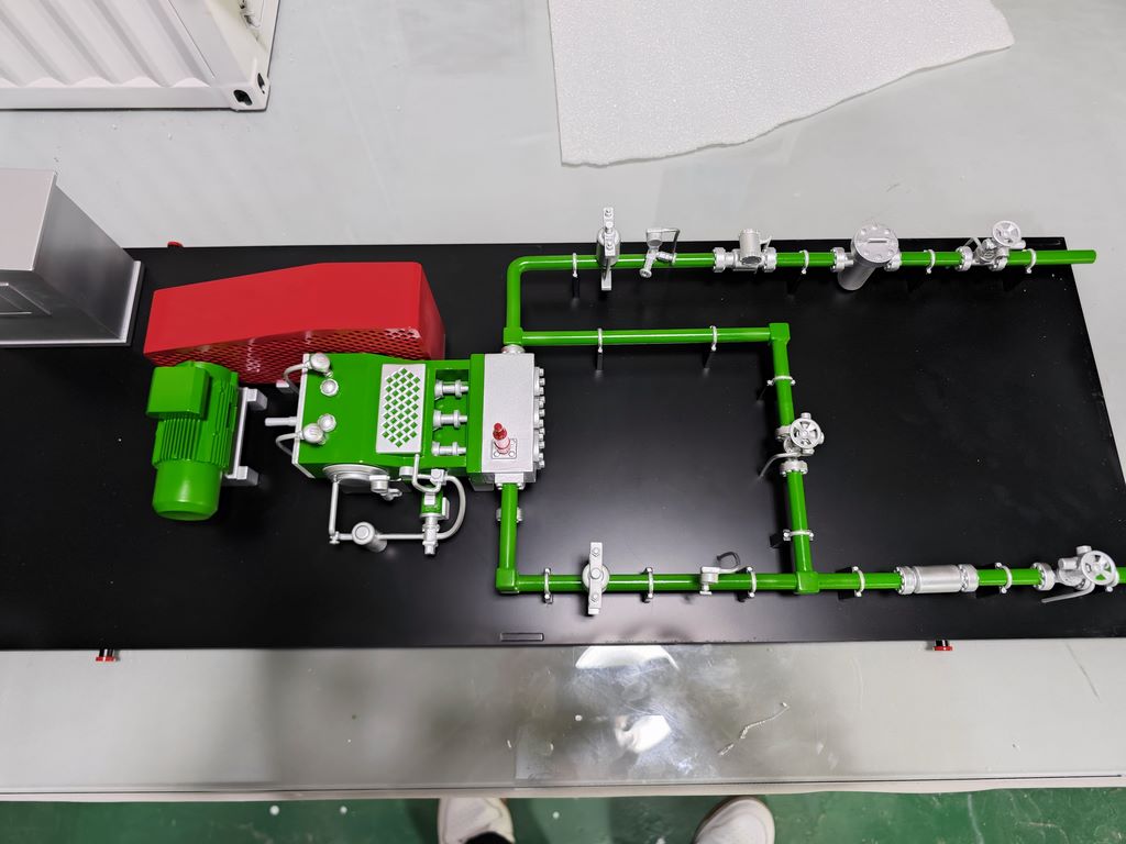
I. Preliminary Research and Design Finalisation
Before project initiation, the technical team first communicated with the client regarding equipment structure and process logic. Then, based on on-site equipment dimensions and component features (such as pipe routing, valve types, and equipment exterior markings), a 1:20 scale 3D model drawing was created. In the drawing, the dimensions and connection methods of the red housing (pre-treatment unit), green pipes (gas conveyance), and white control box (parameter adjustment module) were precisely annotated, serving as the ‘construction blueprint’ for subsequent production.
2. Material Selection and Component Manufacturing
Main Structure: ABS engineering plastic is selected for its balance of strength and flexibility. The outer shells of the red enclosure, green pipes, and white control box are all formed using injection moulding to ensure a smooth surface and precise dimensions; the internal support frame is made from PVC panels cut and assembled to ensure structural stability.
Detailed Components: Valves and connectors on the pipes are made of an aluminium alloy + resin composite material, simulating the metallic texture and connection methods of real equipment; labels on the equipment surface (such as warning labels and parameter nameplates) are printed on PVC film to reproduce the visual information of the equipment.
3. Assembly process: Reproducing the process logic
Model assembly is centred on ‘functional replication’ and strictly follows the actual process flow of the equipment:
Pipe system: Green pipes are welded according to the drawings, with each section of pipe having the same bending angles and valve positions as the actual equipment. Even the ‘pressure-bearing structure’ of the pipes (such as thickened joints) is simulated, making the pipe layout both aesthetically pleasing and consistent with the process logic.
Equipment Connections: Red pre-treatment enclosures are connected to green pipes and white control boxes via ‘simulated flanges/clips,’ replicating the energy and signal transmission logic between equipment; the installation method of green motors (power units) to enclosures also fully replicates the actual equipment's mounting method.
Spatial Layout: The model is placed on a black background panel to simulate the installation environment of the equipment in a machine room. The details of the white walls and ceiling (such as lighting fixtures and maintenance hatches) are also reproduced using PVC panels and spray painting techniques, immersing the model in a realistic scenario.
4. Post-Processing: Faithful Reproduction of Colour and Texture
The model's ‘reproduction accuracy’ is not only in its structure but also in its visual details:
Painting Process: Using a multi-layer spraying technique combined with manual colour adjustment, the colour saturation and gloss of the green pipes and red enclosures match those of the real equipment; the ‘matte texture’ of the white control boxes and the ‘metallic sheen’ of the metal valves are achieved through painting, sanding, and film application techniques.
Detail Polishing: The ‘threaded texture’ of pipe joints and the ‘craftsmanship lines’ on equipment surfaces are meticulously processed using sandpaper and carving tools; even simulated equipment usage traces (such as minor pipe wear and fine scratches on equipment surfaces) are added to enhance the model's ‘realism.’
5. Final verification: 90% accuracy achieved
After the model was completed, the technical team and the client compared it with ‘real equipment photos + drawings,’ ensuring that 90% of the details—from pipe routing, valve types, equipment markings to spatial layout—matched the real equipment exactly. Ultimately, this model not only became a ‘visualisation tool’ for the client to showcase equipment craftsmanship to their clients but also a representative work of our factory's ‘high-fidelity, detail-oriented’ craftsmanship.


